5.9 KiB
| geometry | output |
|---|---|
| margin=2cm | pdf_document |
Raycaster
Michael Zhang <zhan4854@umn.edu>
Determining the viewing window for the raycaster for this assignment involved creating a "virtual" screen in world coordinates, mapping image pixels into that virtual screen, and then casting a ray through each pixel's world coordinate to see where it would intersect objects.
Creating a virtual screen
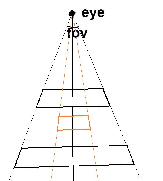
The virtual screen is determined first using the eye's position and where it's looking. This gives us a single 3d vector, but it doesn't give us a 2d screen in the world. This is where the field of view (FOV) comes in; the FOV determines how many degrees the screen should take up.
 {width=180px}
Changing the angle of the field of view would result in a wider or narrower screen, which when paired with the aspect ratio (width / height), would produce a bigger or smaller viewing screen, like the orange box in the above diagram shows. Simply put, FOV affects how much of the frame you're able to see. An example is shown here:
 {width=180px}\
  {width=180px}
The left image uses an FOV of 60, while the right image uses an FOV of 30. As
you can see, the left side has a wider range of vision, which allows it to see
more of the world. (both images can be found in the examples directory of the
handin zip)
Curiously, distance from the eye actually doesn't really affect the viewing screen very much. The reason is the screen is only used to determine how to project rays. As the two black rectangles in the diagram above demonstrates, changing the distance would still allow the viewer to see the same amount of the scene. (using the word amount very loosely here to mean percentage of the landscape, rather than # of pixels, which is determined by the actual image dimensions)
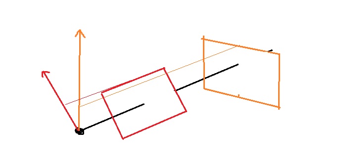
The up-direction vector controls the rotation of the scene. Without the up-direction, it would not be possible to tell which rotation the screen should be in.
 {width=240px}
To see what this looks like, consider the following images, where the left side
uses an up direction of (0, 1, 0), while the right side uses (1, 1, 0) (both
images can be found in the examples directory of the handin zip)
 {width=180px}\
  {width=180px}
Together, all of these parameters can uniquely determine a virtual screen location, that we can use to cast rays through and fill pixels. We can change any of these to produce an image with a more exaggerated view of the scene for example; simply move the eye position to be incredibly close to the object that we are observing, and increase the field of view to cover the entire object.
Because the rays are going in much different directions and travelling different distances, the corners of the image will seem more stretched than if we were observing the object from afar and all the rays are in approximately the same part of the virtual screen.
One other point to make is that we're currently using a rectangle for our virtual screen, which automatically does a bit of the distortion. If instead we were to use a curved lens-like shape, then the rays pointing to any pixel of the screen would be travelling the same distance. Moving the eye position closer to the object would still generate distortion, but to a lesser extent.
Mapping image pixels
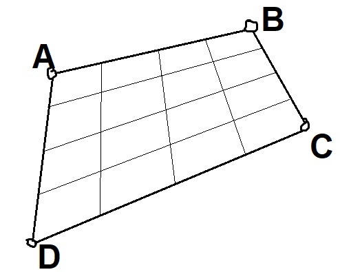
After the rectangle has been determined, we can simply pick one corner to start as an anchor, and then find out what pixel values would correspond to it. For example, in the image below:
 {width=240px}
I would pick a starting point like A, and then take the vector B-A and
subdivide it into 4 pieces, letting \Delta x = \frac{B-A}{4}. Then, same thing
for the y direction, I would set \Delta y = \frac{D-A}{4}. Taking $A +
x_i \times \Delta x + y_i \times \Delta y$ yields the precise coordinate
location for any pixel.
(Technically really we would want the middle of the pixel, so just add
\frac{\Delta x + \Delta y}{2} to the point to get that)
Parallel Projection Notes
Because of the way I implemented parallel projection, it's recommended to
either put the eye much farther back, or use --distance to force a much bigger
distance from the eye for the raycaster. See the --help to see how this option
is used.
Cylinder Intersection Notes
First, we will transform the current point into the vector space of the
cylinder, so that the cylinder location is (0, 0, 0) and the direction vector
is normalized into (0, 0, 1).
This can be done by using a rotation matrix (since we are sure this
transformation is just a rotation). This rotation is actually a 2D rotation,
around the normal between the cylinder direction and (0, 0, 1). We then
rotate everything we are working with (the cylinder and the ray) into this
coordinate system to make calculations easier.
Then it's a matter of determining if the x and y coordinates fall into the
space constrained by the equation $(o_x + t\times r_x - c_x)^2 + (o_y + t\times
r_y - c_y)^2 = r^2$ and if z \le L. I can solve this using the quadratic
formula the same way as the sphere case.
We want a quadratic equation of the form At^2 + Bt + C = 0. The values for
A, B, and C are:
A = r_x^2 + r_y^2B = 2(r_x(o_x - c_x) + r_y(o_y - c_y))C = (c_x - o_x)^2 + (c_y - o_y)^2 - r^2
Solving this for t yields 0-2 solutions depending on if the equation was
satisfied or not. Then, we can plug any solutions we get back into the ray
equation and determine if the $z$-coordinate is in the range of the cylinder
that we want.
We will also have to do this for the ends of the cylinder, but just backwards.
So we would start with the $z$-coordinate, solve for $t$s where the ray hits
that $z$-plane, and then check the x and y values to see if they satisfy the
ray equation as well.